Land foundation for wind turbines in the IJsselmeer
Land foundation for wind turbines in the IJsselmeer? This requires a fundamentally different design approach. How did we at ABT and WINDBASE, in collaboration with SwifterwinT, TU Delft, Vattenfall, Aratis, GEvernova and Ballast Nedam, arrive at this solution? Read the English version of the article by colleagues Paul Schraven, Thomas Lankreijer, and Casper Meijer that was published in the latest edition of Land+Water.
Land foundation for wind turbines in the IJsselmeer
For the design of the 24 foundations of wind turbines in the IJsselmeer near Lelystad, a different approach instead of a traditional monopile was made. After extensive research, a Cofferdam construction was chosen. The stiffness requirements from the turbine supplier and the collision load were among the design determinants.
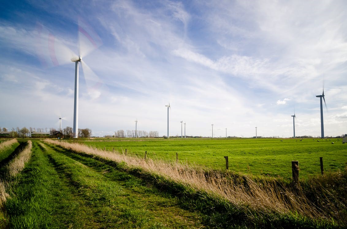
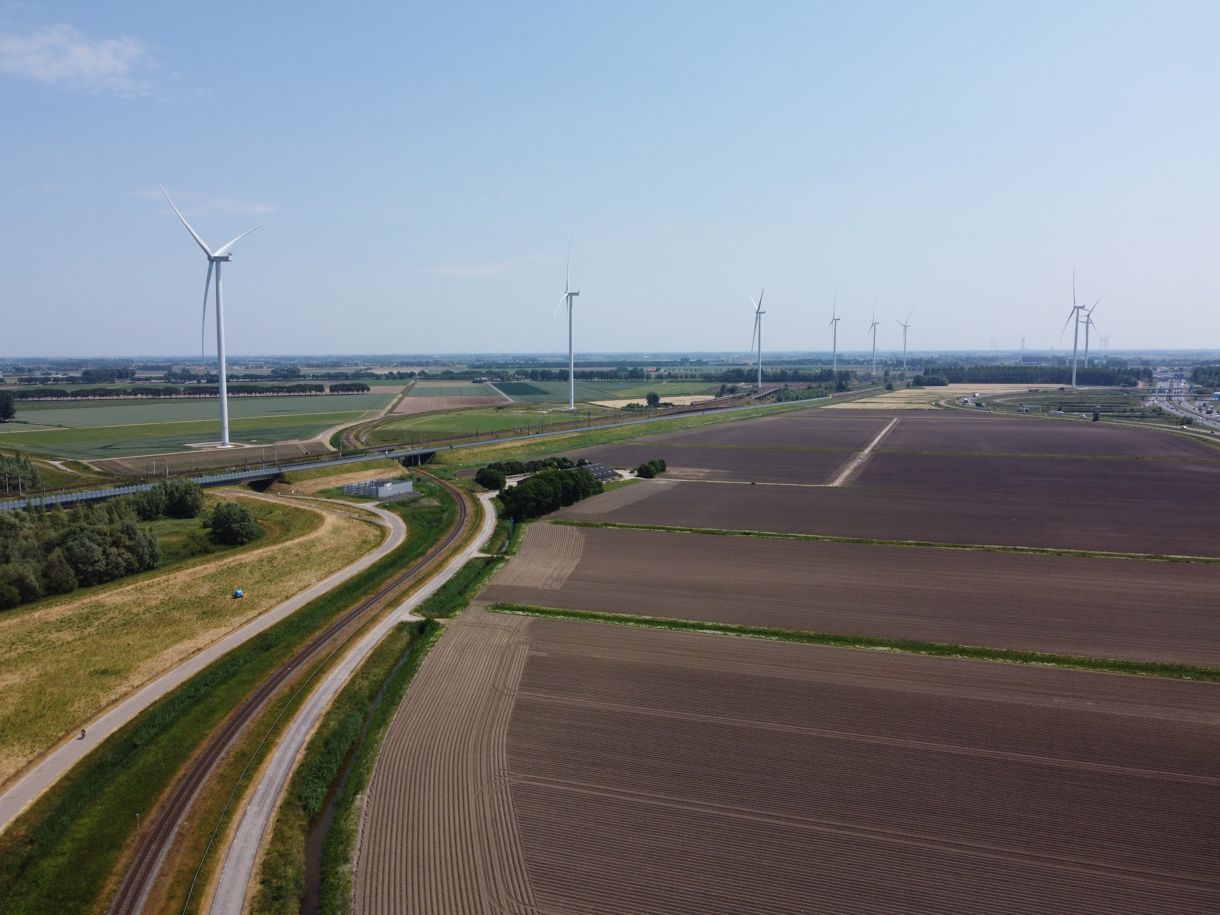
Along the dike between Lelystad and Swifterbant, the view has changed remarkably in recent years: the iconic Irene Vorrink wind farm has been replaced by 24 imposing wind turbines on the IJsselmeer. These nearshore foundations are part of the larger project Windplanblauw, which involves replacing 74 old wind turbines: 37 onshore and 24 nearshore. When operational, the entire wind park will have a capacity of approximately 340 MW, providing enough electricity for the consumption of 450,000 households (about 1 million Dutch residents).
Dolphin or Cofferdam
Given the size of the turbine and the relatively shallow IJsselmeer, placing a land-based turbine in the IJsselmeer proved to be the best solution. Two promising foundation solutions were considered: the Dolphin construction and the Cofferdam constructions. The Dolphin construction consists of a system of vertical steel foundation piles with a concrete pedestal placed on top. The turbine can then be tensioned using prestressed anchors, similar to the practice with onshore turbines. The Cofferdam is a circular combined wall construction made of steel foundation piles with double Z-sheetpiles in between. The foundation is filled with sand to provide additional stiffness and strength, allowing it to better withstand various loading scenarios. On top of the foundation piles, a concrete pedestal is placed to support the turbine.
Basis of Design
In order to apply a land foundation in a near shore environment, it is necessary to adopt a fundamentally different design approach. A variety of factors that are typically applicable in either on-shore or marine environments must be integrated. These factors include the need to address ice loads, collision loads, scour, hydraulic conditions, and to translate typical land turbine-related requirements, such as "no-gapping" and "dynamic stiffness," to nearshore conditions. In order to translate these effects into design constraints, a Basis of Design (BoD) was established, outlining the practical design conditions. Some of the most significant conditions within this Basis of Design (BoD) pertain to the practical handling of ice and collision loads. In order to determine the requisite ice loads, recent measurements and an extrapolation of ice thicknesses from the IJsselmeer were employed by Deltares. Furthermore, in cooperation with TU Delft, a straightforward calculation model was devised to ascertain the maximum ice load on a range of structural components, including continuous walls and slender steel foundation piles. Although an ice load scenario is highly improbable, it could potentially affect the entire wind park. Consequently, special load cases – ULS & SLS ice (ultimate limit state & serviceability limit state) – were considered, ensuring that the turbine park remains fully operational even after such an event.
Deformed mesh of the turbine foundation after a collision load
Maritime research
A maritime study was conducted by Marin to assess the collision probabilities of different turbines with shipping vessels, given that the new turbines are positioned on both sides of the fairway. While the individual collision probabilities at each turbine location are relatively small, the cumulative chance of a random collision with a CEMT Class Va inland vessel (a large Rhine ship) was significant when considering all turbines. This cumulative risk was taken into account during the Basis of Design (BoD) phase.
After consultation with the wind park operator, an AL (Accidental Limit State) approach was selected in the event of a head-on collision. This approach allows for the structure to be written off, after which the turbine must be dismantled in a safe manner. The BoD involved a pushover analysis of the foundation. An energy balance was established, converting the ship’s kinetic energy during a collision into crumpling of the ship’s hull and plastic deformations of the foundation structure. The crumpling of the ship’s hull was calculated according to both the ROK (Guidelines for Structural Design) and the DNV standard (Det Norske Veritas).
Proof of concept & design
Following the completion of the BoD and prior to the tendering process and drafting the contract based on UAV-gc (Uniform Administrative Conditions for Integrated Contracts), the two promising foundation variants (Dolphin and Cofferdam) were investigated and developed up to preliminary design (PD) level. This step demonstrated the feasibility of the design principles.
Key dimensions, such as the concrete diameter and indicative lengths/dimensions of the foundation piles, were determined. These dimensions remained relatively unchanged in the subsequent Detailed Design (DD) phase carried out by the contractor. For the design, advanced PLAXIS 3D analyses were conducted to calculate stresses in the foundation piles. The sheet piles and foundation piles were modeled as shell elements, with Z-profiles accurately connected to the steel foundation piles using predefined degrees of freedom to correctly represent the system’s stiffness.
Innovative construction principles
The analyses confirmed the feasibility of both design principles. A trade-off led to the selection of the Cofferdam as the optimal solution, which was then further developed in the DO phase. Ballast Nedam worked on the DO, including reinforcement design, with Windbase serving as an advisor to Windplan Blauw in the reviewing role within the SCB contract (System-Oriented Contract Management).
The contractor subsequently refined innovative construction principles, such as the installing frame for the steel foundation piles, the prefabricated lost formwork and reinforcement elements. Optimization was also carried out regarding the collision load to be considered. An interesting yet crucial detail was the cable routing to the turbine. The contractor opted for J-tubes attached to the sheet pile walls.
Execution
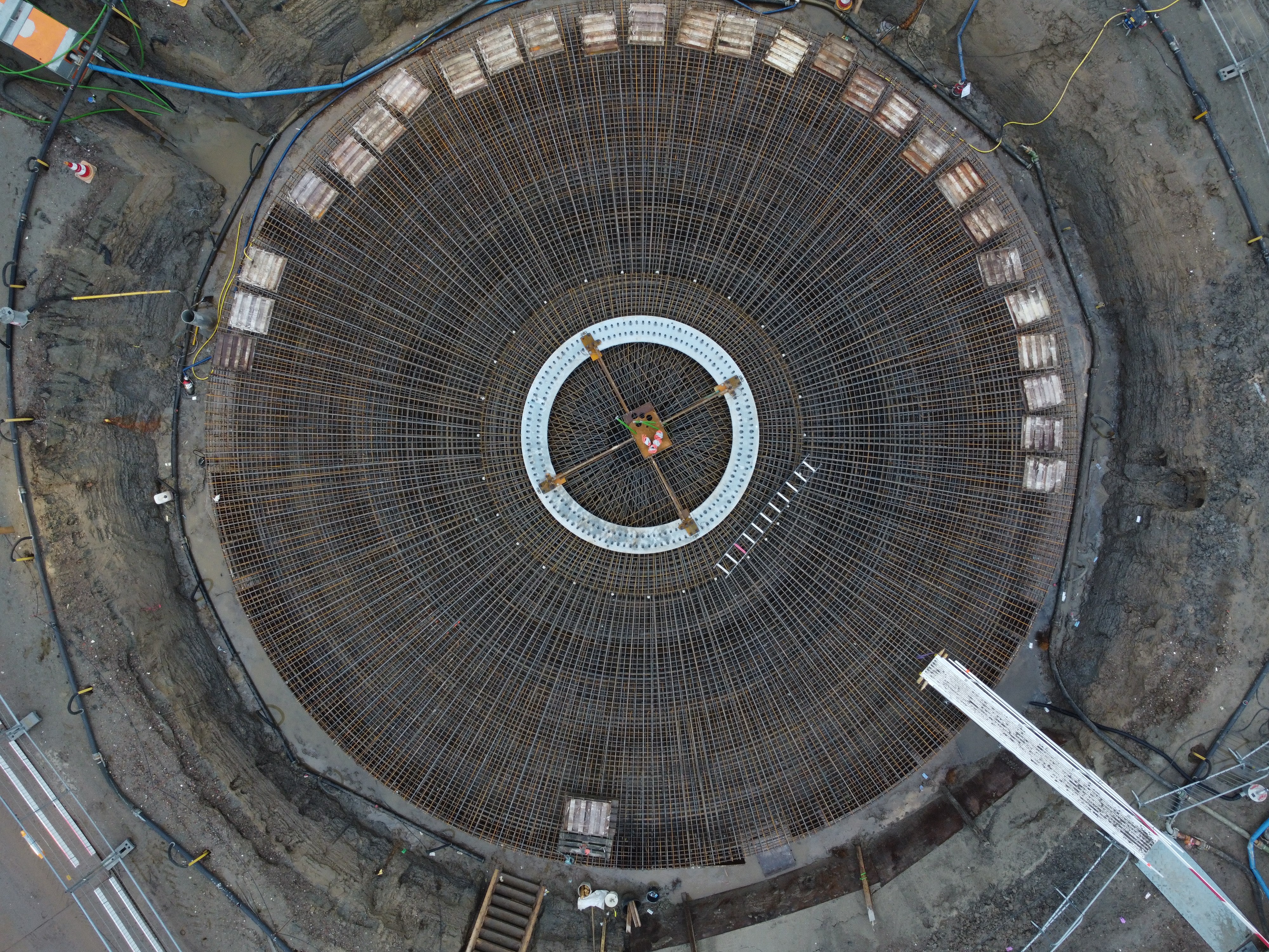
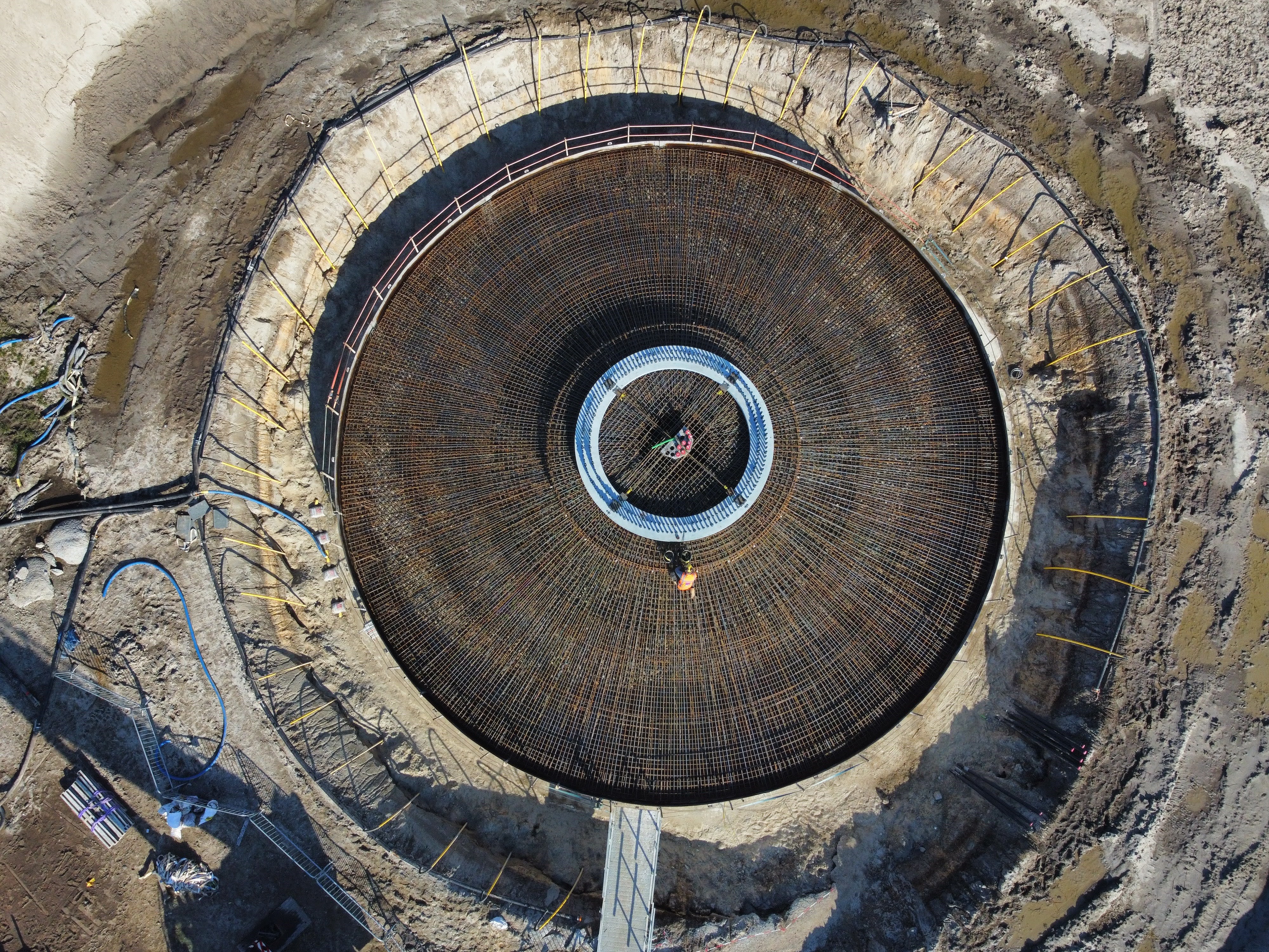
The use of prefabricated elements simplified the construction of the foundations and allowed for multiple operations. Construction began with the placement of four auxiliary piles with an H-frame. From this H-frame, the 22 steel foundation piles were accurately driven in a circular pattern to the required depth. After installing the steel foundation piles, sheet pile, the ring beams and the J-tubes were added. The foundations were then filled with moderately compacted sand. Prefabricated L-walls formed a large formwork into which the concrete base was poured. The exterior of the L-walls features an aesthetically which serves as a visual signal for future navigation in the waterway. Once the formwork was in place, the anchor cage as the core reinforcement was installed followed by the lifting of seven large reinforcement cages. The final step involved manual tying of the rebar to close the reinforcement cage. Using a floating concrete pouring plant, approximately 900 m³ of concrete was poured for each foundation. This base ring serves as the starting point for the tower and acts as the interface between the foundation work and the turbine structure. Once the grout had been applied and allowed to set, the 152 anchors securing the tower base ring to the foundation were pre-tensioned and safety features such as fencing, stairs and a davit crane were installed.
The pouring of the concrete in the foundation
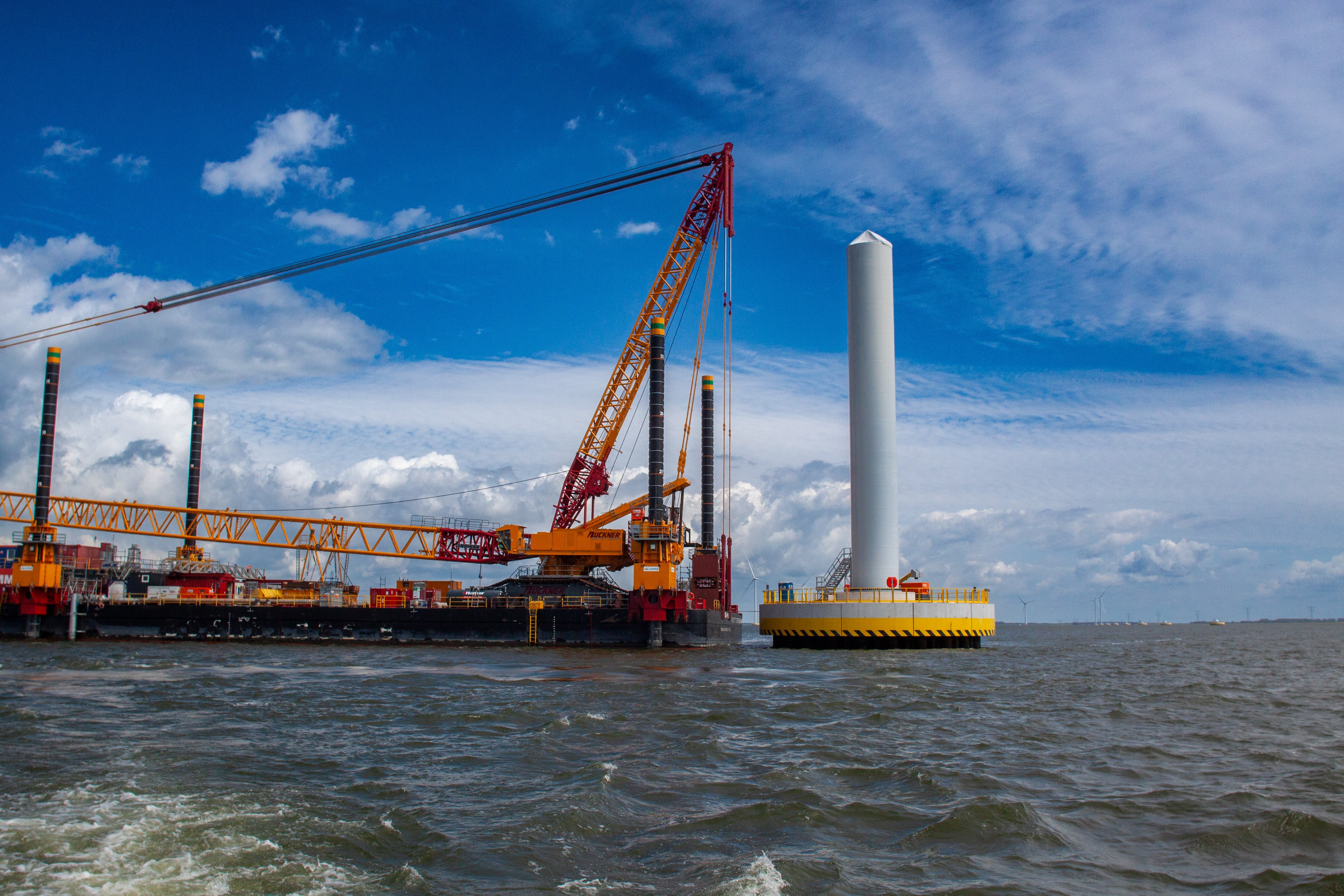
Once the foundation contractor had completed the work, the various turbine components were lifted into place. For this purpose, a 1350-tonne crane was mounted on a special barge (a small ship) equipped with spud piles (which extend through the ship to the bottom of the lake). Mammoet designed this installation. To ensure the stability of the barge, third parties conducted dynamic interaction calculations based on standard soil profiles, wind directions and wave heights occurring in the IJsselmeer. At each turbine location, at least three spud pile positions were defined based on cable positions and in the subsoils, to allow for safe lifting operations.
Conclusion
The installation of the final wind turbine was completed on 20 March. We can reflect on a period of learning, during which complex calculations were carried out using Plaxis 3D and DIANA. These demonstrated that a land-based turbine on a nearshore foundation in the IJsselmeer meets the specified requirements and can be certified and installed.
Authors:
Paul Schraven: Design Lead
Thomas Lankreijer: Geotechnical Advisor
Casper Meijer: Senior Quality Inspector (all working at ABT and its subsidiary, WINDBASE)