foundations

See here how we do that....
See here how we do that....
Services
Pleased to meet you...
WINDBASE is the new name in the wind energy world and originates from the Dutch engineering company ABT. ABT has a long track record in civil engineering for wind energy projects and is known for its optimised foundation designs. Same team, different name: WINDBASE, Dutch pioneers, smart engineers.
Projects
Foundations for over 2800 wind turbines, 180 wind farms, 2600 MW of installed wind power in 27 countries. 80000 m3 of concrete and 12000 tons of steel saved, due to our advanced calculation techniques.
The first time a gravity based foundation has been designed on a primary sea dike. The sensitive soils and the earthquake area make this an unique and challenging project!
About us
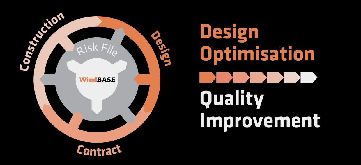
We believe that ultimate quality of the end product can only be achieved when design, contract and construction are considered as a total concept. The involvement of the designer in all phases is crucial for identification and mitigation of risks. This model connects our ambition for optimised designs to a high quality.
Windbase works according to the conditions for quality management as mentioned in NEN-EN-ISO 9001:2015 and is certified by Lloyds. Durability is anchored within the Windbase organisation and its advisory work. Windbase is a CO2-neutral organisation and applies the most recent environment management systems. Windbase is in possession of the ISO 14001 certificate.
Certificates
- ISO 14001:2015 (2023)
- ISO 9001:2015 (2023)
- Organizational Safety Culture Certificate Step 3 (ABT, 2022)
- CO2-Conscious Certificate Level 5 (2022)